
VoIP Telephony
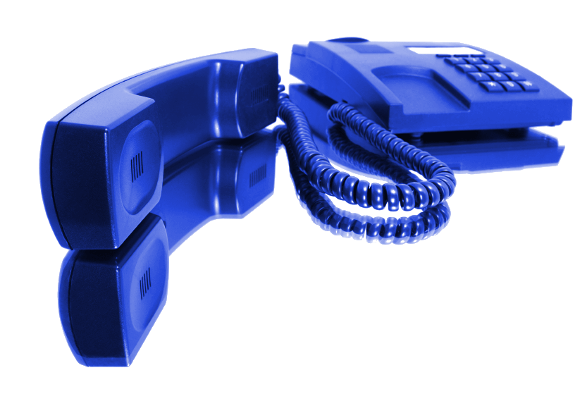
Provide maintained PoE power to VoIP handsets and telephony equipment, protecting continuous office and call centre operation. Install at central, office workgroup or individual handset locations to suit your system requirements.
CCTV Surveillance

Achieve 24/7 viewing with no device re-boot downtime. Avoid interruptions to crucial video analytics. Install in any convenient location and add the benefits of uninterrupted edge recording and remote power status monitoring to your system.
Intercom & Call Point
Provide maintained power to all PoE intercoms and call points. Ensure that clients, visitors and the public can always contact you when it is important.
Access Control
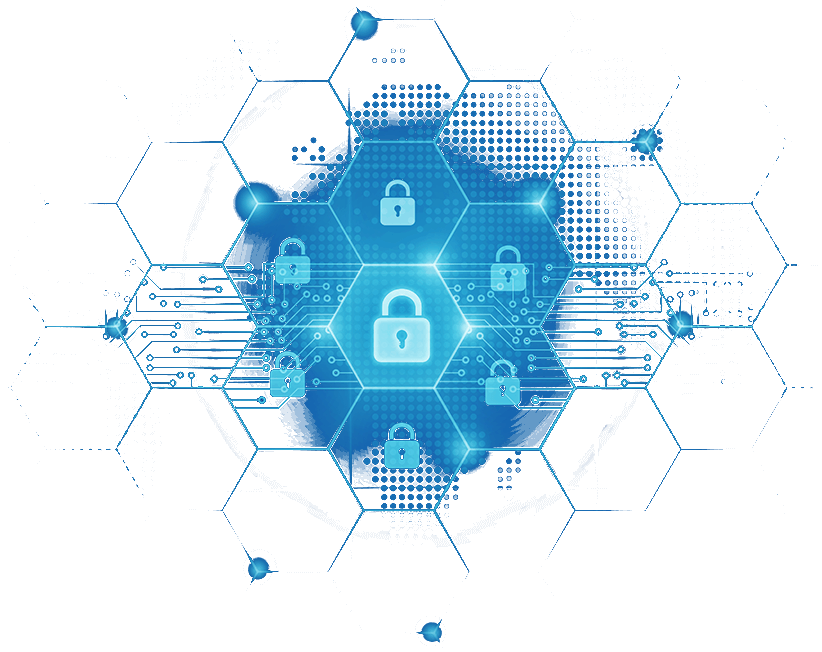
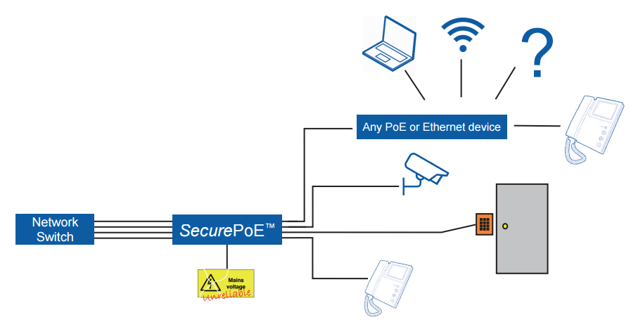
Reliably power PoE access control equipment from the most suitable locations with a secure maintained supply. Suited to both 'centralised' and 'local to door' controller installation layouts, SecurePoE offers security and power monitoring features for interfacing with your chosen platform.
Lighting
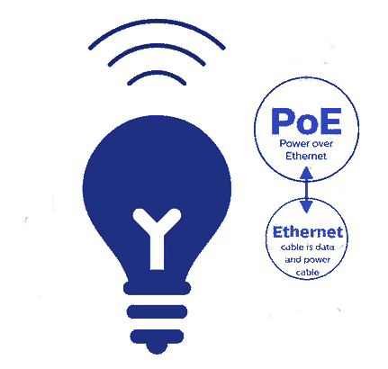
Provide back-up battery power for PoE lighting systems, allowing office, retail, industrial and domestic space to remain safer for use during power outages. Whether for display, staff, public or private areas, you can keep the lights on for longer.
Cluster Devices
Integrate and simplify systems by clustering device types to power them from one unit while adding security and stand-by capability. For example, power and maintain an intercom, CCTV camera, door controller and lock, all from the same SecurePoE device.
Scale Systems
Provide SecurePoE features for systems ranging from a single device to large installations. Use wall-mounting, indoor and outdoor options to suit. Select options with or without battery stand-by and with or without integral Ethernet switch.
Upgrade

Add SecurePoE to existing PoE power capability, whether powering additional PoE devices, upgrading equipment or supplementing inadequate PoE availability limited by existing power budgets. SecurePoE units can be added to all existing systems.
Protect

Prevent accidental or deliberate disconnection with all terminations inside a secure enclosure. Monitor PoE power status, mains power status, battery status and lid tamper status to give alerts when an event occurs.
Capability
Provide continuous 30W PoE power from each output 100% of the time without any 'power budget' limitation. Power any IEEE802.3:2012 compliant PoE powered device (802.3af, 802.3at, PoE, PoE+).
Power considerations
Security system components have varied power needs: a supply of direct mains, specified DC or AC low voltage, or PoE (Power over Ethernet). Often systems will use a mixture of supply voltages due to the requirements of individual components. Power distribution decisions should be based on key factors such as reliability, continuity, accessibility, compliance, physical security and cost. Many system devices are capable of functioning with more than one type of supply. Surveillance cameras might accept a low voltage AC or DC input as well as PoE power.
Security systems consist of pathways carrying information between system components and pathways distributing power. With networked systems these two types of interconnecting path can be located separately, follow a similar route or be physically combined. System power can be planned much like a simple data network, with the incoming power branching out, via PSUs and power storage devices, to the various components. A good design will minimise power transmission bottlenecks, reduce single points of failure and consecutive points of potential failure within each path.
Mains back-up generators and UPS systems may be pre-existing at a location or specified for installation. These can be helpful but should be scrutinised with regard to acceptability, including the effect of a unit failure.
IP security devices such as surveillance cameras tend to 'reboot' following a power interruption, resulting in a loss of coverage during the reboot period, which can last anything up to 90 seconds. The use of a dedicated maintained power supply local to devices ensures seamless operation. The prevention of device reboot downtime makes a powerful case for the use of battery-maintained power supplies in all security applications, as does the continuous provision of functions like edge storage, door entry and call-point access, regardless of mains and network state.
It is more reliable to use power supplies that are separate from network infrastructure. Separation of power provision removes single points of failure, reducing both the likelihood and the magnitude of failures. Good dedicated power units normally have higher life expectancies than switching equipment.
All PSUs have a conversion-efficiency loss which is shed as heat, potentially affecting other equipment. Network devices with integrated power outputs may have a 'power budget', limiting the defined output power to a specified total figure, rather than providing full capability to all outputs.
This allows the possibility of load devices being connected with insufficient power available. With some supply products it is possible to overload the integrated power supply, resulting in a shutdown of all outputs until the overload is removed. As some common devices have variable power consumption, it is a risk that these will appear to function normally until loads demand higher power levels.
While convenient, the use of integrated power outputs for critical operations is questionable. The specification of separate PSUs will improve system reliability.
Given sensibly specified power supplying equipment, bottlenecks in power distribution paths are a function of voltage supplied, power demanded and wire conductor size used. These bottlenecks manifest as resistive 'volt drop'. Conductors have an inherent resistance at a given temperature and the degree of volt drop is inversely proportional to the voltage supplied. Ohm's law dictates that for any known conductor and power conducted, a doubling of supply voltage will half the current, hence also halving the voltage drop. Importantly, the resulting transmission power loss is actually quartered as a result of doubling the voltage, due to the halving of the current conducted and the resultant halving of the volt drop. Subsequently it is preferable to use available higher voltages until within the area of load devices, which commonly means using mains power. At the load device area, a secure PSU or PoE midspan can be sited, including battery back-up if required.
The IEEE standard for PoE devices ensures power losses will be acceptable within a 100 metre span. Non-compliant PoE devices are an unknown and a potential hazard. To reduce points of failure in a power path it is necessary to minimise the number of power conversion stages. Supplying mains voltage to the load area (or where not possible the next highest available voltage) then using one or more low voltage power supplies keeps the path as simple as possible. For normal practical purposes and as a requirement for PoE supplies, installation of the low voltage PSUs should be within 100 metres of the load devices. If necessary, these can be sited alongside network apparatus such as edge switches and media converters, as well as being status monitored dependent on system requirement.
Power repeaters designed for consecutive placement in a power path can save up-front cost but give multiple failure points in the path. They are also inefficient, having a conversion efficiency loss at every stage.
The applicable standard defining the requirements of all compliant PoE devices is IEEE802.3:2012. This incorporates the earlier standard amendments 802.3af (2003) and 802.3at (2009). The 'af' and 'at' references continue to be seen. Two device power categories exist: up to 15.4W ('af') and up to 30W ('at' or PoE+). It is sensible to specify the 30W supplies as this allows the connection of any PoE standard compliant device.
The choice of conventional versus PoE power is often debated. Both methods are valid. Whichever is used, the consideration of minimising losses, separating power, removing failure points and spreading risk between multiple power supply units will enable the design of reliable systems.